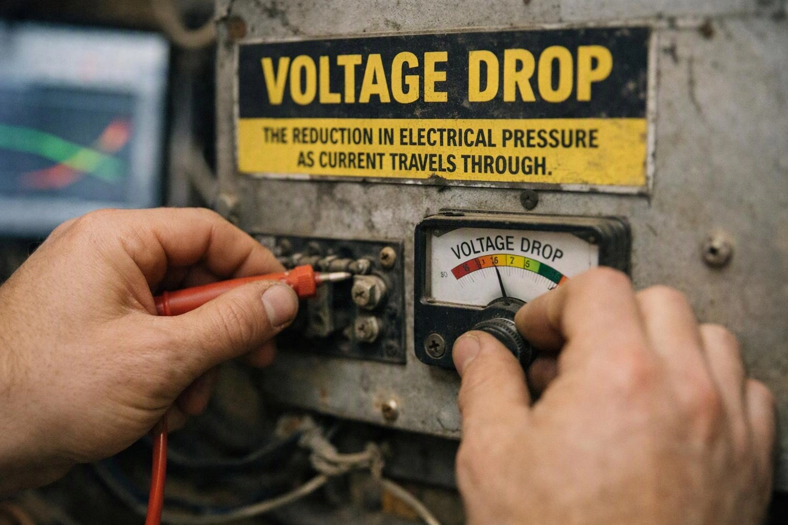
What is Voltage Drop?
Voltage Drop is the reduction in electrical voltage that occurs as current travels through a conductor, connection, or other circuit component. The reduction results from electrical resistance and increases with longer wire runs, higher current, or undersized conductors. Excessive Voltage Drop can cause dim lights, motor problems, heat, and unreliable equipment operation.
Quick Facts About Voltage Drop
Category
Electrical circuit performance
Formula
Voltage loss equals current multiplied by resistance
Measured by
A multimeter at the source and load
Common confusion
It is not the same as low utility voltage
Also called
Voltage loss, Line drop
Often discussed with
Electrical Troubleshooting, Electrical Safety Inspections
Key Takeaways About Voltage Drop
- Voltage Drop increases as wire length, circuit current, or conductor resistance increases.
- A voltage reading at the panel may look normal while equipment receives less voltage.
- Long runs and motor loads require careful conductor sizing and voltage-drop checks.
- Excessive loss can cause dimming, overheating, nuisance trips, or poor motor performance.
Understanding Voltage Drop

Voltage Drop describes voltage lost as electricity moves through a circuit. Every conductor has some resistance. Part of the source voltage pushes current through the wire. A short copper conductor usually loses little voltage. A long run or small conductor can lose much more.
Related glossary terms: Ampere, Copper Wiring, Load Calculation.
The load receives the voltage left after the loss. For example, a 120-volt circuit loses 6 volts. It delivers about 114 volts at the equipment. The loss can affect lighting, receptacles, heating equipment, and motors. Voltage Drop is a circuit condition. It isn't always a utility problem or defective appliance.
How Voltage Drop Works, Is Measured, or Is Used?
The basic relationship is V = I × R. V means voltage loss. I means current in amperes. R means resistance in ohms. Resistance rises with conductor length. Resistance falls with a larger cross-sectional area. Copper and aluminum have different resistance values. Temperature changes also affect conductor resistance.
An electrician checks the source voltage first. Then, the electrician checks voltage at the operating load. The difference shows circuit loss under that load. A proper test considers both circuit conductors. A 100-foot one-way run has about 200 feet of circuit path. This applies to a typical single-phase circuit. Useful checks include:
- Measure voltage with the equipment off and while the equipment operates.
- Compare the measured loss with the design target and applicable code guidance.
- Inspect terminals, splices, and disconnects for heat or loose connections.
- Check conductor size, circuit length, load current, and operating conditions.
Why Voltage Drop Matters?

Excessive loss reduces voltage available to the load. Incandescent lights may appear dim. Electronic equipment may reset. Motors may draw more current while struggling to start. A loose terminal or damaged splice can create concentrated resistance. This resistance may produce heat. The wire size may still appear correct.
The condition also affects design decisions. A circuit may have a correctly sized circuit breaker. It may still deliver poor performance at a distant load. Corrective options can include a larger conductor or shorter circuit path. They can also include a lower-current load or connection repairs. The selected remedy must match equipment ratings. It must also match overcurrent protection and installation requirements.
When Voltage Drop Matters Most?
Voltage Drop deserves close attention on long branch circuits. It also matters in detached structures and workshops. It matters on circuits serving high-current equipment. Motors for pumps, compressors, furnaces, and air conditioners need special care. Starting current can be several times higher than running current. A circuit may work under light demand. It may show a serious problem when the motor starts.
Designers also review voltage loss for EV chargers, electric heat, welders, and other heavy loads. The National Electrical Code includes voltage-drop informational notes. These notes guide design. Equipment instructions may set tighter limits. In Pittsburgh homes and commercial buildings, older wiring can affect performance. Remodeled spaces and long basement or garage runs can also matter. Measured performance may help more than a panel-only voltage reading.
How to Evaluate Voltage Drop?
- Measure voltage at the source and at the operating load, then subtract the load reading from the source reading.
- Record the load current during testing because Voltage Drop changes as current changes.
- Inspect every terminal, splice, disconnect, and receptacle for heat, discoloration, or looseness.
- Verify conductor material, wire gauge, circuit length, load rating, and breaker size.
- Compare the result with equipment instructions and applicable National Electrical Code design guidance.
Related Concepts Compared
Voltage Drop vs. Low Voltage
Low voltage describes a supply or system operating below its expected level. Voltage Drop describes the loss between a circuit source and its load.
Voltage Drop vs. Resistance
Resistance is the electrical property that opposes current. Voltage Drop is the resulting voltage loss when current flows through that resistance.
Voltage Drop vs. Power Loss
Power loss describes energy converted into heat or other forms. Voltage Drop is measured in volts, while power loss is commonly measured in watts.
Voltage Drop vs. Wire Gauge
Wire gauge identifies conductor size. A larger conductor generally has lower resistance and can reduce Voltage Drop on a given circuit.
Expert Note
A voltage test with no load can miss the problem. Measure at the equipment while the circuit carries its normal current, then repeat during motor startup or another demanding condition when practical.
Common Mistakes or Myths About Voltage Drop
- Checking voltage only at the breaker panel and not at the operating equipment.
- Ignoring loose terminals because the conductor size appears adequate.
- Sizing a circuit from breaker amperage without considering distance and load current.
- Confusing Voltage Drop with a utility supply problem.
- Using a larger breaker to hide a voltage problem, which can create an unsafe condition.
Voltage Drop in Practice: A Real-World Example
A detached garage has a 120-volt receptacle circuit with a long underground run. The panel measures 121 volts, but a saw operating at the garage receives 112 volts because of conductor resistance and a loose connection. The saw runs poorly, and the warm connection requires immediate investigation.
Sources & Further Reading on Voltage Drop
Related Terms
Ampere
Ampere is the SI unit of electric current. It measures how much electric charge passes a…
Copper Wiring
Copper Wiring is an electrical conductor system that uses copper wire to carry power or signals…
Load Calculation
Load Calculation is a method for determining how much electrical power a building, panel, or circuit…
Wire Gauge
Wire Gauge is a standardized measurement of a conductor’s diameter and electrical capacity. The American Wire…
Electrician Pittsburgh
Have Questions About Voltage Drop?
Contact Electrician Pittsburgh for practical guidance on Voltage Drop and related 24 hour electrician work in Pittsburgh.