Electrical Troubleshooting: Fault Types, Testing Methods, and Diagnostic Tools
Electrical troubleshooting uses fault types, testing methods, and diagnostic tools to identify electrical problems. Electrician Pittsburgh uses visual inspection, circuit testing, load checks, and thermal imaging to locate unsafe connections, overloaded circuits, breaker problems, and other electrical defects.
Get a Free EstimateOptions at a Glance
Each troubleshooting method answers a different question about a circuit. Our team selects the method that matches the symptom and the suspected fault.
What Electrical Troubleshooting Can Reveal
Electrical troubleshooting reveals where a circuit is failing and whether the cause involves wiring, connections, loads, or protective devices.
An electrical fault can affect a circuit, an electrical load, or a protective device such as a circuit breaker. We trace the symptom to the affected wiring or connection, then use a diagnostic reading to confirm the cause.
Our findings can show why an outlet stops working, why breaker tripping continues, or why equipment receives unstable power. The result supports a focused repair recommendation.
Common Electrical Fault Types and Their Warning Signs
Common electrical faults include short circuits, open circuits, ground faults, overloads, loose connections, voltage drops, and arcing. Warning signs help us decide where to begin testing, but symptoms alone do not confirm the fault.
| Type | Key Features | Cost | Best For |
|---|---|---|---|
| Short circuit | An unintended low-resistance path can cause protective-device operation. | Varies | Locating sudden loss of power or breaker operation |
| Open circuit | A broken path stops current from reaching part of the circuit. | Varies | Dead outlets, lights, or equipment |
| Ground fault | Current takes an unintended path to ground. | Varies | Repeated protective-device operation and safety concerns |
| Overload | Electrical load exceeds what the circuit can safely support. | Varies | Circuits that trip during equipment use |
| Loose connection | A poor terminal or splice can create resistance and heat. | Varies | Flickering, heat, or intermittent operation |
| Voltage drop | Voltage decreases along a circuit because of resistance or load conditions. | Varies | Weak equipment performance and dimming |
| Arcing | Electricity jumps across a gap and may create heat, noise, or marks. | Varies | Burning smells, crackling, or visible damage |
We treat burning smells, crackling, heat, and visible damage as safety concerns. Our crew isolates the affected circuit before deeper testing.
Which Troubleshooting Methods Match Each Fault?
The right troubleshooting method depends on whether the suspected problem affects voltage, continuity, resistance, current, load behavior, or heat. We combine methods when one diagnostic reading cannot confirm the fault.
| Method | What It Checks | Common Use |
|---|---|---|
| Visual inspection | Visible condition | Damage, heat, corrosion, and loose parts |
| Voltage testing | Electrical potential | Supply, neutral, and ground checks |
| Continuity and resistance testing | Path and resistance | De-energized conductors and connections |
| Current measurement and load testing | Electrical current under use | Overloaded branch circuits |
| Thermal imaging | Heat patterns | Hot connections and overloaded components |
Visual Inspection for Visible Electrical Damage
Visual inspection is a direct check for burn marks, damaged insulation, loose terminals, corrosion, and other visible electrical damage. We inspect accessible wiring, devices, junction boxes, and the electrical panel before selecting a test.
Visible damage can point to arcing, overheating, moisture exposure, or a failing connection. We do not rely on appearance alone when a circuit remains energized or unsafe.
Voltage Testing for Energized Circuit Problems
Voltage testing checks whether an energized circuit has expected electrical potential between line voltage, neutral, and ground. We use a voltage tester or multimeter to compare readings at relevant points.
Voltage testing can reveal an open neutral, a supply issue, or a voltage drop. Our team follows electrical safety procedures because energized circuit testing carries shock and arc risks.
Continuity and Resistance Testing for De-Energized Circuits
Continuity testing checks whether a complete path exists in a de-energized circuit, while resistance testing measures opposition to current through a conductor or connection. We isolate power before using these methods.
A broken conductor, damaged cable, or poor connection can produce an unexpected result. We use the reading with circuit information and visual findings to confirm the fault.
Current and Load Testing for Overloaded Circuits
Current and load testing measures electrical current while a circuit operates under its actual electrical load. We use a clamp meter to assess a branch circuit without disconnecting the conductor.
An overloaded circuit can trip its protective device or produce heat at weak points. Our team compares current behavior with the circuit layout and connected equipment before recommending a repair.
Circuit Tracing for Hidden Wiring Problems
Circuit tracing follows a cable or branch circuit between devices, a junction box, and the electrical panel. We use a circuit tracer when labels are unclear or a hidden wiring path needs identification.
Tracing helps connect a symptom at an outlet or switch to the correct protective device. We document the path before testing or changing a connection.
Thermal Imaging for Heat-Related Electrical Faults
Thermal imaging uses a thermal camera to show infrared energy and identify abnormal heat patterns. We use infrared inspection to look for a hot connection, an overloaded component, or uneven heating in an electrical panel.
A hot spot does not prove one specific fault by itself. We pair thermal findings with current measurement, visual inspection, and circuit testing before preparing a repair recommendation.
Which Diagnostic Tools Do Electricians Use?
Electricians use diagnostic tools that measure voltage, current, resistance, continuity, insulation condition, circuit paths, and heat patterns. Our tool selection depends on whether the circuit is energized, de-energized, accessible, and safe to test.
A digital multimeter supports voltage, resistance, and continuity checks. A non-contact voltage tester provides a preliminary indication of voltage, while a clamp meter measures current around a conductor.
An insulation tester evaluates insulation condition, a circuit tracer identifies circuit paths, and a thermal camera shows heat patterns. A receptacle tester can help identify certain outlet wiring conditions, but it cannot find every electrical problem.
We combine tools with circuit knowledge and safe work practices. A tool reading without the right test setup can lead to the wrong conclusion.
How We Troubleshoot an Electrical Problem
We troubleshoot an electrical problem by documenting the symptom, making the circuit safe, testing the suspected sections, confirming the fault, and explaining the repair path.
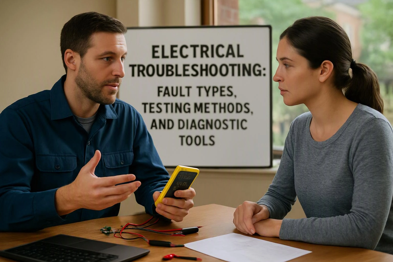
We record useful findings so the repair decision is based on evidence from the circuit. For service information, see Electrical Troubleshooting.
Why Does a Circuit Breaker Keep Tripping?
A circuit breaker keeps tripping when the circuit detects excessive current or a fault such as an overload, short circuit, ground fault, or failing connected device.
A faulty appliance can create the symptom only when it operates. We isolate connected loads, inspect the breaker panel, and test the branch circuit to separate an equipment fault from a wiring problem.
Repeated breaker operation is not a condition to ignore. We investigate the cause instead of repeatedly resetting the protective device.
Can Thermal Imaging Detect Electrical Problems?
Yes, thermal imaging can detect abnormal heat patterns that may indicate loose connections, overloaded components, or developing electrical faults, but the result requires follow-up testing.
Thermal imaging detects infrared energy at the surface of equipment and can reveal a hot spot that is not visible during a standard visual inspection. We use the image to guide further voltage, current, or connection checks.
Thermal imaging is especially useful during an electrical safety inspection when equipment is operating under a meaningful load. Our Thermal Imaging Electrical Testing process connects the heat pattern to the circuit evidence.
What Electrical Troubleshooting Can You Safely Do Yourself?
You can safely note symptoms, unplug a suspect appliance, and reset a breaker once when no danger signs are present; exposed wiring, burning smells, shocks, repeated trips, and heat require Electrician Pittsburgh to investigate.
Do not touch exposed wiring or open equipment when you see damage or feel unsure about the circuit. You can keep people away from the area and provide our team with the symptom details.
Electrical safety depends on knowing whether a circuit is energized. We handle testing and repairs when the problem involves wiring, panels, connections, or repeated protective-device operation.
What Changes the Cost of Electrical Troubleshooting?
Electrical troubleshooting cost changes with the fault location, circuit accessibility, testing required, equipment involved, and whether the inspection identifies a repair need; Electrician Pittsburgh provides Free Estimates Available.
Faults inside an accessible device can require a different testing path from faults hidden in a cable, junction box, or electrical panel. Thermal imaging, circuit tracing, and load testing may also change the work scope when symptoms are difficult to isolate.
Our estimate explains the observed condition, recommended testing or repair, and the work included. Contact us for an exact quote based on the property and the confirmed fault.
When Electrical Troubleshooting Needs a Safety Inspection
An electrical safety inspection is appropriate when symptoms suggest broader wiring, grounding, panel, outlet, or overheating concerns beyond one isolated fault.
We recommend a wider inspection when several outlets or switches show problems, when the electrical panel shows heat or damage, or when grounding concerns appear during testing. Our team checks the affected systems and documents the findings.
A safety inspection can also help when an older installation has unclear circuit labeling or repeated unexplained faults. We use the results to separate urgent concerns from planned repair work.
Get Electrical Troubleshooting Guidance
Electrician Pittsburgh can evaluate electrical symptoms, select the appropriate testing method, and explain the findings and repair options.
We provide a diagnostic report when the work calls for documented findings, along with a repair recommendation that connects the fault to the proposed scope. Our team can also explain when thermal imaging or an electrical safety inspection adds useful evidence.
Contact Electrician Pittsburgh to discuss the symptom and request an exact quote for the required troubleshooting work.
Questions About Electrical Troubleshooting Methods
What is the difference between a short circuit and a ground fault?
Electrician Pittsburgh explains a short circuit as an unintended connection between points with different electrical potential, while a ground fault sends current onto an unintended grounding path. We test the affected circuit to identify which condition is present.
Why are some electrical faults difficult to locate?
Some electrical faults are difficult to locate because the symptom may occur only under load, inside hidden wiring, or at an intermittent connection. We combine circuit tracing, load checks, visual inspection, and targeted measurements to narrow the fault.
Can a multimeter find every electrical problem?
A multimeter cannot find every electrical problem because some faults appear only under load, through heat patterns, or along a hidden circuit path. We use the multimeter with other tools and inspection methods when the symptoms require broader testing.
What does a circuit tracer identify?
A circuit tracer identifies the path of a cable or branch circuit between connected devices and the electrical panel. We use the result to match an outlet, switch, or junction box with its protective device.
When should thermal imaging be used during an electrical inspection?
Thermal imaging should be used when operating equipment may reveal abnormal heat at a connection, component, or electrical panel. We use the thermal image as a guide and confirm the finding with circuit testing.